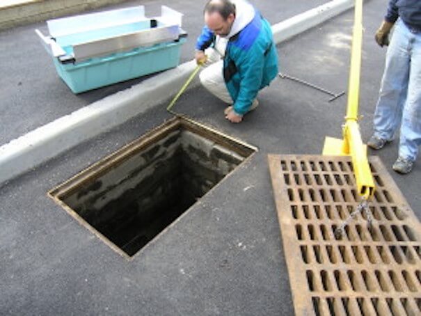
Measuring Grates for storm basin installation
Measuring grates is easy now. Fabco Industries has added a brand new page to the company website for those looking to install our highly effective storm water filtration systems into pre-existing drains. In the new section titled “Measuring Grates,” we offer step-by-step instructions on measuring the physical dimensions of an existing drainage inlet of both the round and rectangle variety. Having this information readily available makes it easier than ever to retrofit a Fabco catch basin insert to an existing drain; the sooner we have the size of measuring grates, the quicker we can engineer and install your stormwater filtration system.
Measuring grates on storm drains for Fabco’s StormBasin™, StormSack™, StormSok™, and StormPod™ are all considered catch basin insert filters. These filter products are designed to be installed under the grate of a typical storm drain inlet. In this position, any runoff water directed to the drain must first pass through the filter before it travels through the rest of the underground stormwater system.
Catch basin insert filters can treat a variety of pollutants at this entry point effectively cleaning the water before it is combined with potentially clean water downstream. Click on the link to learn more about measuring grates round or rectangular.
Stormwater Measuring Grates Resources
A highway storm-drainage facility collects stormwater runoff and conveys it through the roadway right of way to adequately drain the roadway and minimize the potential for flooding and erosion to properties adjacent to the right of way. A storm-drainage facility consist of curbs, gutters, storm drains, side ditches or open channels (as appropriate), or culverts.
The placement and hydraulic capacity of a storm-drainage facility should be designed to consider damage to adjacent property and to secure as low a degree of risk of traffic interruption due to flooding as is consistent with the importance of the road, the design traffic service requirements, and available funds. Stormwater pollution-prevention requirements should be considered and addressed in the design process of each storm-drainage system. The following is a summary of the policies for pavement drainage system design and analysis.

Bridge Deck A zero gradient, sag vertical curve, or superelevation transition with a flat pavement section should be avoided on a bridge. The desirable longitudinal grade for bridge-deck drainage is 0.5% or steeper, especially for new construction. A flatter grade will be tolerated where it is not physically or economically desirable to satisfy this criterion. A bridge may not require drainage facilities.
The quantity and quality of runoff should be maintained as required by applicable stormwater regulations. See Chapter Thirty-three for additional information.
Curbs, Inlets, and Turnouts Curbs, inlets, or turnouts are used where runoff from the pavement can erode fill slopes, or where reduction of the right of way needed for shoulders, side ditches, or open channels, etc., is desirable. Where storm drains are necessary, the pavement section should be curbed.
Design Frequency The design flood frequency for roadway drainage is related to the allowable water spread on the pavement and design speed. This design criterion is discussed in Section
Detention Storage Reduction of peak flow can be achieved through the storage of runoff in a detention basin, storm drainage pipe, swale, side ditch, open channel, or other detention storage facility. Stormwater can then be released to the downstream conveyance facility at a reduced flow rate. The concept should be considered where existing downstream conveyance facilities are inadequate to handle peak flow rates from a highway storm-drainage facility.
A developer may not be permitted to increase runoff over existing conditions, thus necessitating a detention storage facility. Additional benefits include the reduction of downstream pipe sizes and the improvement of water quality by removing sediment or pollutants.
Gutter-Flow Calculations Gutter-flow calculations are necessary to relate the quantity of flow to the spread of water on a shoulder, parking lane, or pavement section. A composite gutter section has a greater hydraulic capacity for a normal cross slope than a uniform gutter section, and is therefore preferred. See Section 36-8.0 for additional information and procedures.
Hydrology The Rational Method is the most common method in use for the design of a storm drain if the momentary peak flow rate is desired. Its use should be limited to a system with a drainage area of 200 acres or less. A minimum time of concentration of 5 min is acceptable. The Rational method is described in Chapter Twenty-nine.
Inlets The term refers to each type, such as a grate inlet, curb inlet, or slotted inlet. A drainage inlet is sized and located to limit the spread of water on traffic lanes to a tolerable width for the design storm in accordance with the design criteria.
The width of water spread on the pavement at a sag should not be substantially greater than the width of spread encountered on a continuous grades. A grate inlet or depression-of-curb-opening inlet should be located outside the through traffic lanes to minimize the shifting of a vehicle attempting to avoid it. A grate inlet should be bicycle-safe if used on a roadway that allows bicycle travel.
If a grate inlet is used at a sag location, a double curved vane grate should be utilized to compensate for plugging that can occur. 2012 Where significant ponding can occur, such as at an underpass or sag vertical curve in a depressed section, flanking inlets should be placed on each side of the inlet at the low point in the sag. See Section 36-9.03 for a discussion on the location of inlets.
Manholes The maximum spacing of access structures whether manholes, junction boxes, or inlets should be approximately 400 ft. Figure 36-11B is useful in determining the relationship between manhole diameter, maximum pipe size, and deflection angle as defined in Figure 36-13B.
Roadside or Median Ditch A large amount of runoff should be intercepted before it reaches the highway to minimize the deposition of sediment or other debris on the roadway, and to reduce the amount of water which must be carried in the gutter section.
A median area or inside shoulder must be sloped to prevent runoff from the median area from flowing across the pavement. A surface channel should have adequate capacity for the design runoff and should be located and shaped to not present a traffic hazard.
Where permitted by the design velocity, a channel should have a vegetative lining. An appropriate lining may be necessary where vegetation will not control erosion. See Chapter Thirty for detailed hydraulic information on a channel.
Storm Drain A storm drain is defined as a closed-conduit system. It consists of that portion of the storm drainage system that receives runoff from inlets and conveys the runoff to a point where it is then discharged into a side ditch or water body. At least one end is connected to a manhole, inlet, catch basin, or similar structure. A pipe which is connected to an inlet located in a paved median, grassed median, or lawn area is considered a storm-drain structure.
A storm drain should have adequate capacity so that it can accommodate runoff that enters the system. It should be designed considering future development if appropriate. The storm-drain system for a sag vertical curve should have a higher level of flood protection to decrease the depth of potential ponding on the roadway or bridge. Where feasible, the storm drain should be designed to avoid existing utilities.
The storm-drain outfall should be designed to ensure that the potential for erosion is minimized. The drainage-system design should be coordinated with the proposed staging of a large construction project to maintain an outlet throughout the construction project. A storm-sewer trunk line should be located behind the curb or, if not practical, under the roadway without being located in the wheel path. 2012 Design the main and all laterals as a system.
The system must not operate under pressure for the design storm. The hydraulic grade line must not exceed a manhole, catch basin, or inlet rim elevation for the check storm. The placement and capacity should be consistent with local stormwater management plans. A minimum pipe size of 12 in. with a minimum velocity of 2.5 ft/s is desirable to prevent sedimentation from occurring in the pipe.