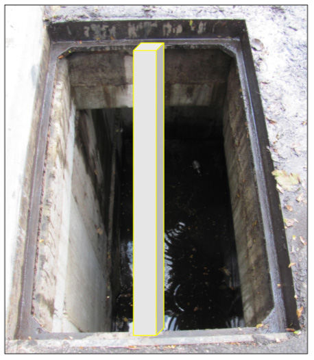
Stormwater Inlet Grate Frame and Inlet Clear Space Considerations
Review Information Needed on Grate Frame and Clear Space Openings and Recording it on the Survey Form
All Fabco Industries Water Quality Inserts (WQIs) are manufactured to properly fit inlets by using specific information compiled in a survey of the “as-built” inlet. The Fabco Grate/Inlet Survey form serves as the tool to provide that information.
Recording Grate Frame and Inlet Clear Space Considerations
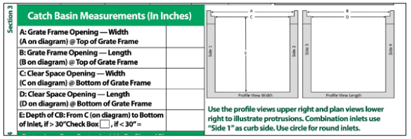
Section 3 of the Fabco Industries survey form captures the dimensions of the grate frame opening and clear space opening, as well as the depth of the inlet.
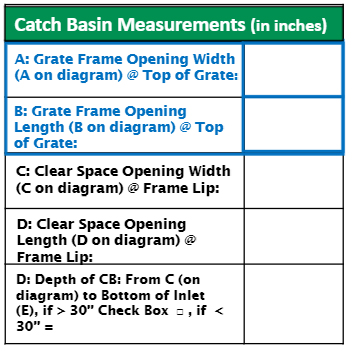
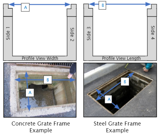
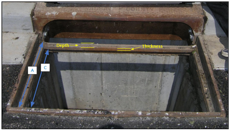
Measurement A:
The distance of the grate frame opening at the top of the grate in the width direction
The elevation of measurement A is illustrated in the profile view width above.
Measurement B:
The distance of the grate frame opening at the top of the grate in the length direction
The elevation of measurement B is illustrated in the profile view length above.
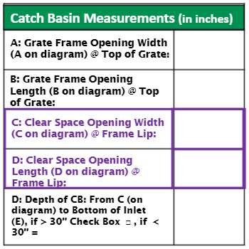
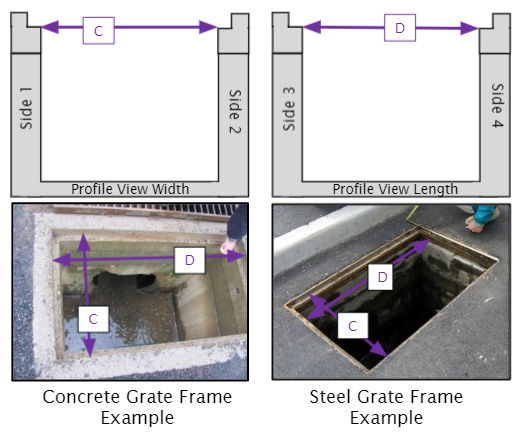
Measurement C:
The distance of the grate frame opening at the bottom of the grate in the width direction
The elevation of measurement C is illustrated in the profile view width above.
Measurement D:
The distance of the grate frame (or opening) at the bottom of the grate in in the length direction
The elevation of measurement D is illustrated in the profile view length above.
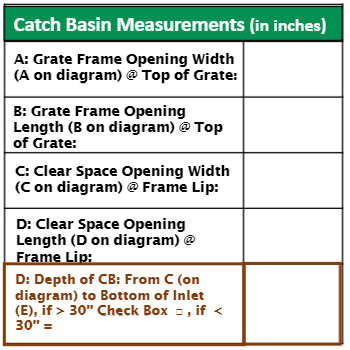
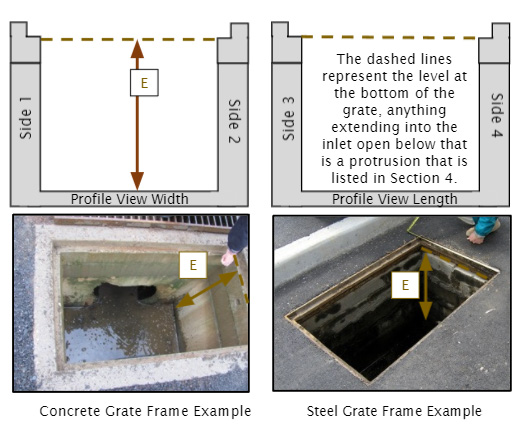
Measurement E:
The distance of the depth from the bottom of the grate to the bottom of the inlet.
Contractors Note:
The intent of Section 3 is to obtain accurate dimensions of the grate frame a nd grate frame opening at the bottom of the grate (dashed lines in the profile views above). Anything below that level that extends beyond the grate frame opening into the open inlet space (concrete ledges, bricks, etc.) is a protrusion that is listed in Section 4.
The grates for these inlets are usually foundry manufactured. Providing cut sheets for the actual grate purchased for the target inlets can help determine and verify details of the grates. Please include any grate documentation along with the submitted survey forms.
See Below for Additional Help With Unique Inlets:
Combination Inlet with Four Sided Frame:
Some combination grates will have a fourth side to the frame, as opposed to just the open curb throat. Generally, the fourth frame support will be straight and create a square or rectangular frame, even if the curb throat casting refelcts a radius.

When surveying these types of frames, the length and width measurements should easily be recorded in Section 3, lines A, B, C & D. It is important to record the other dimensions of the fourth frame support, depth and thickness, as indicated below:
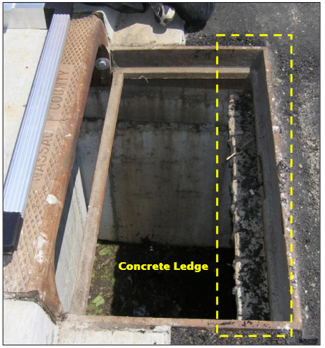
Anything extending into the inlet clear space below the bottom of the frame is considered a protrusion and is captured in Section 4 of the survey form. Below is an example of a protrusion into the inlet clear space. In this case, a ledge created by the top of the wall of the precast concrete inlet. Because the top of the ledge is below the bottom of the grate frame, this is considered a protrusion that is recorded in Section 4.
Contractors Note:
When an inlet frame or clear space has any features that do not have an existing space to fill on the survey form, please sketch it out as best as possible with measurements on a separate piece of paper or any open space on the survey form.
Pictures of the grate, framea nd inlet clear space provide valuable information for Fabco’s engineers when they review and design the inlet insert.
When working with multiple inlets, and taking pictures of the grate, frame and inlet clear space, having a number designation for future reference can save significant time during the design as well as the installation process. This designation can be on a small white board, piece of paper, written in chalk or by any number of other means. Using a oil based Sharpie pen to mark the grates is an easy way to designate inlet identification numbers during the survey process.
Gusseted Frames:
Some foundry frames will have gussets in the corners or along the frame or both, as pictured below. It is important to provide those measurements to assure the Fabco inserts fit the frame.
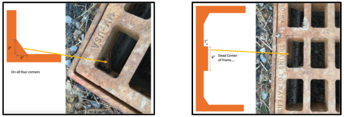
Fabco manufactures frame/flange systems that will adapt to gusseted frames, as pictured below.

Support Bars:
There are some grate frames that will have an additional support bar, generally in the length direction. Fabco does not recommend these bars be permanently removed. Collect the relevant measurements of the bar and confirm that it can be temporarily removed during the insert installation process. Photo documentation is also very helpful. Fabco will create a frame that can be installed while the bar is removed, yet allows the bar to be reinstalled after insert placement.
