Measuring Open Curb Inlet Pipes and Protrusions
Review Information Needed on Open Curb Inlet Pipes and Protrusions and Recording it on the Survey Form
All Fabco Industries Water Quality Inserts (WQIs) are manufactured to properly fit inlets by using specific information compiled in a survey of the “as-built” inlet. The Fabco Grate/Inlet Survey form serves as the tool to provide that information.
Measuring Open Curb Inlet Pipes and Protrusions
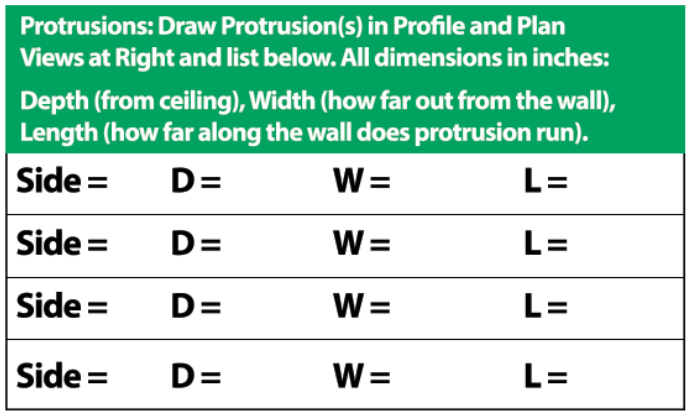
Pipes:
Every inlet will have a minimum of at least one pipe (to discharge the flow). Some inlets may have multiple pipes. It is important for Fabco to understand the size and location of the inlet pipes, even if they do not protrude into the inlet open space as the Fabco filter device should not impede the flow in either direction
Example One: Concrete Discharge Pipe
The pipe is located on the front wall of the inlet where the curb throat opening is located. This is Side 2 of the structure per the guidance drawing on the form and at right.
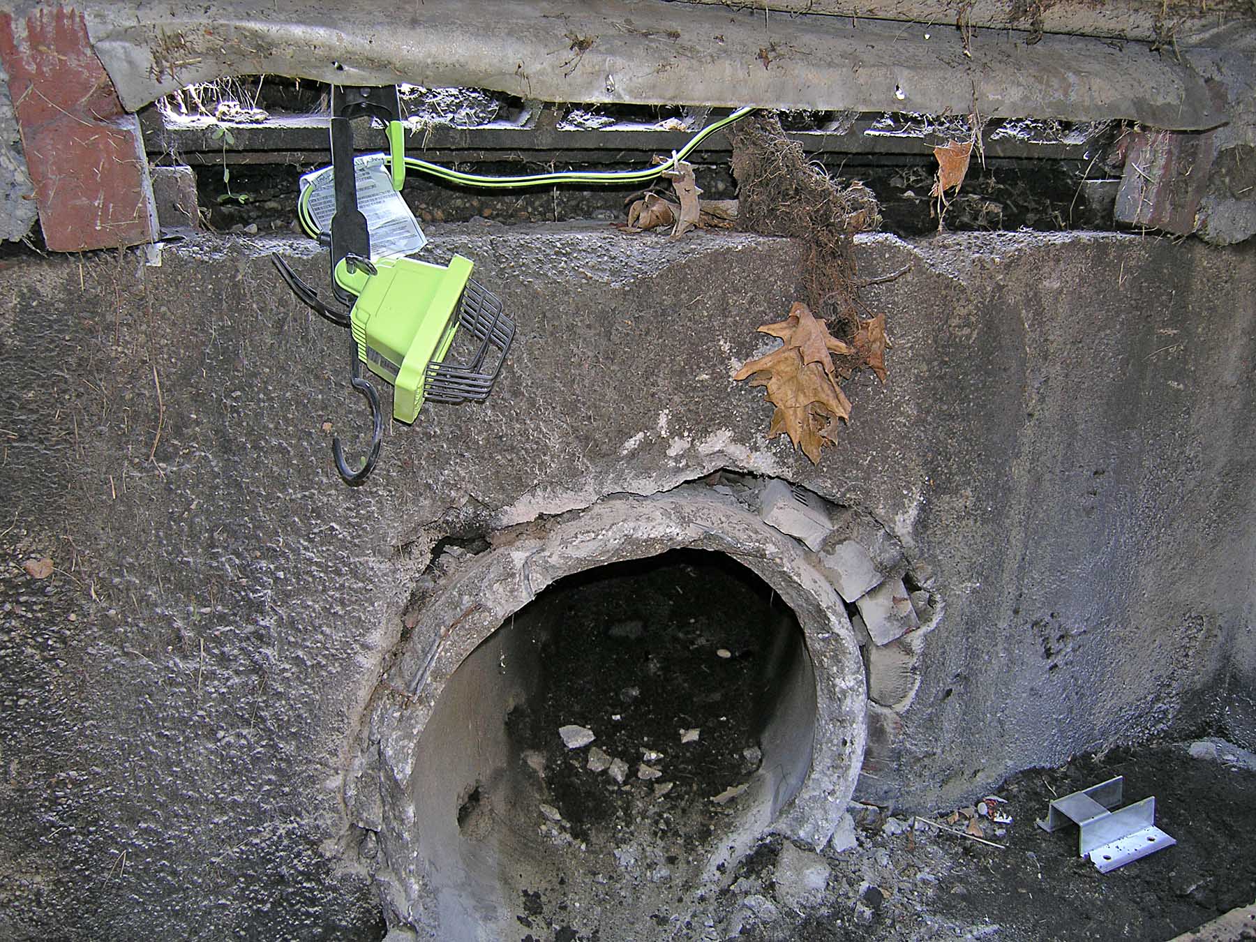
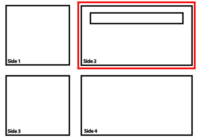
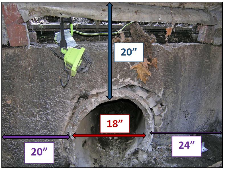
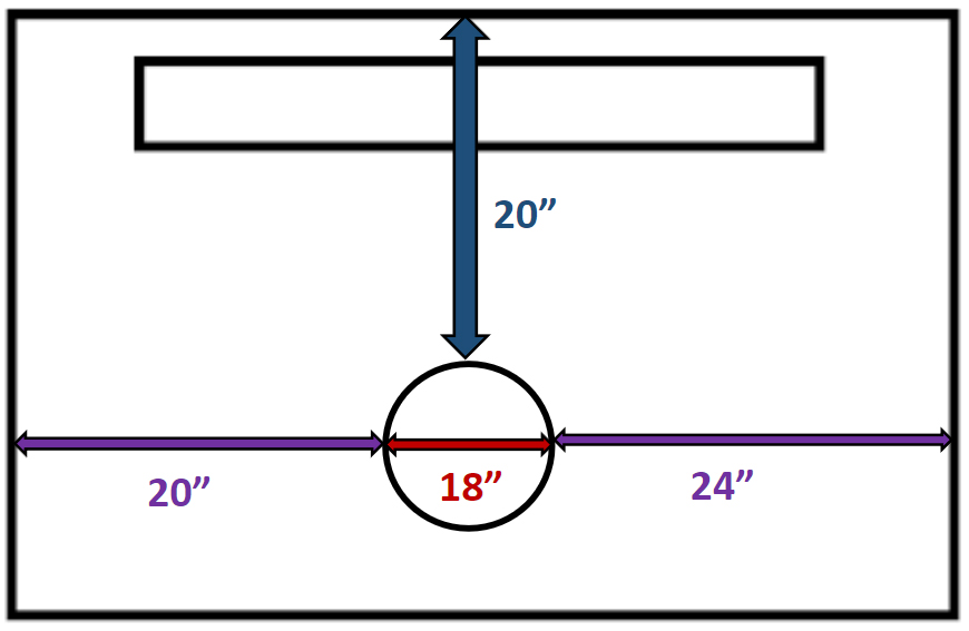
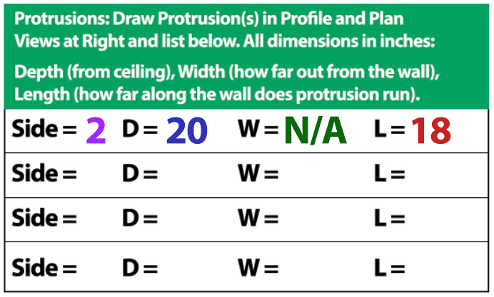
”D”: The top of the pipe is 20” below the elevation of the ceiling of the inlet so is recorded as D = 20 on the P/P chart on the form.
”W”: The Pipe is flush with the inlet wall – so it is recorded as W = N/A. Although the pipe does not protrude into the inlet clear space, its dimensions and location must still be recorded on the form. See Example two below for protrusions other than pipes.
“L”: The pipe diameter is 18”, and is recorded as “L = 18“ on the P/P chart. The profile views of the interior of the inlet at the bottom of the Open Curb Inlet Survey Form provide the space to include where along the wall the pipe is situated (see purple measurements on either side of the pipe image and profile view of side 2).
Example Two: Ladder Rungs
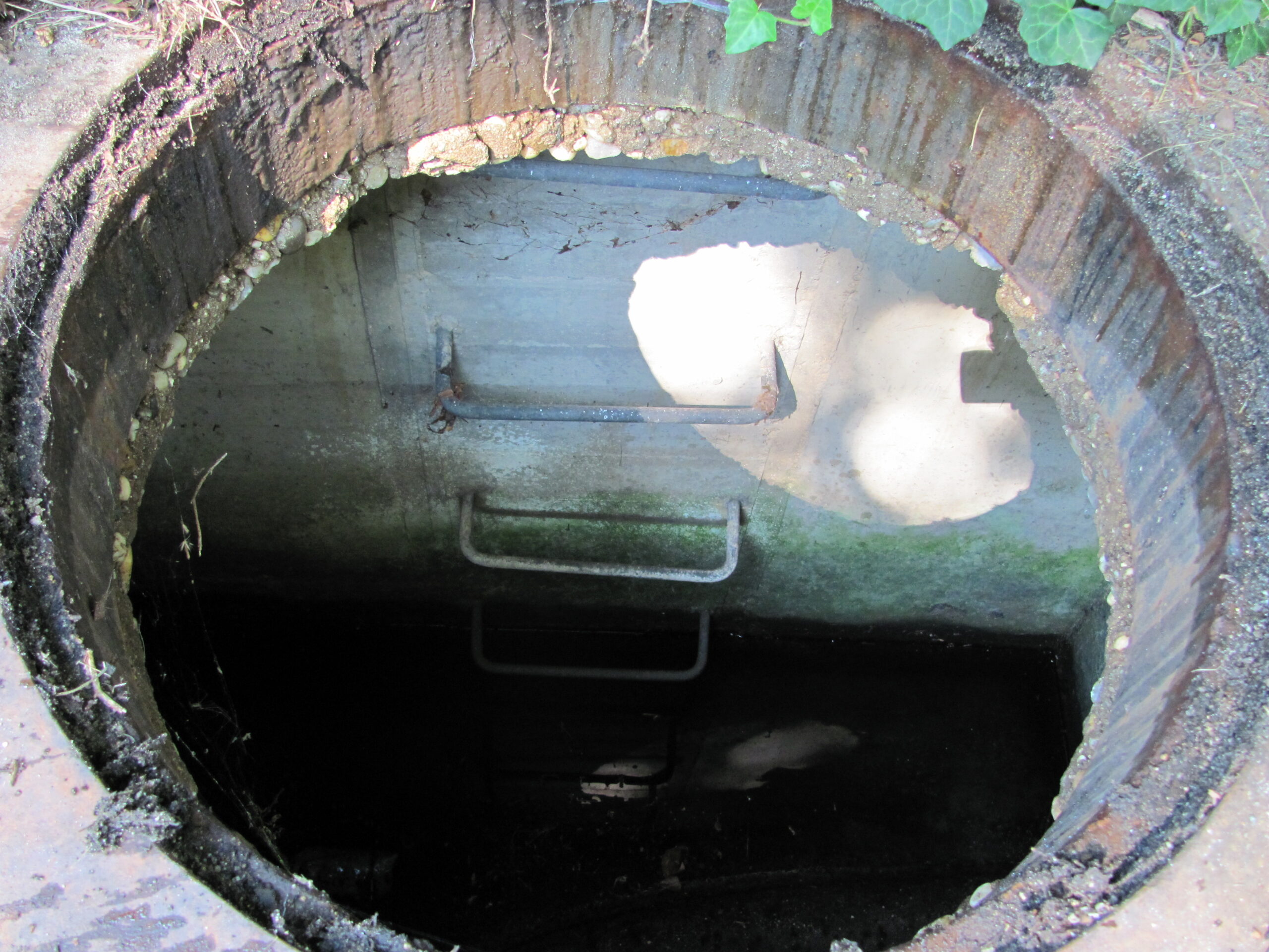
This example is also a model for any other protrusion into the inlet’s open space, such as ledges, bricks or any other potential obstacle to the Fabco device in the inlet.
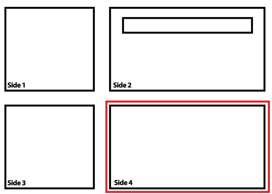
The rungs are on the back wall of inlet, across from the Side 2 with the curb throat. This is Side 4 of the structure per the guidance drawing on the form and at right.
14” wide, extend out from the wall approx. 6 inches, run up and down the entire wall height and are centered on the 64” wide back wall.
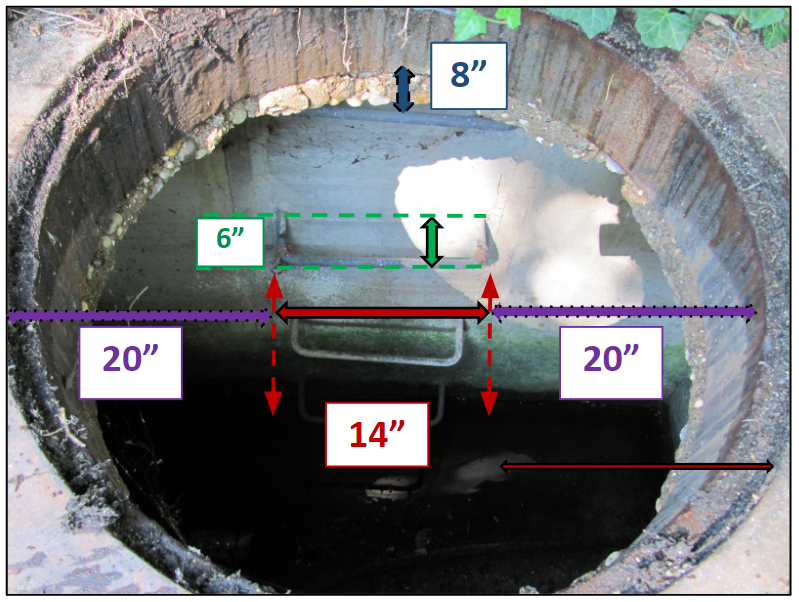
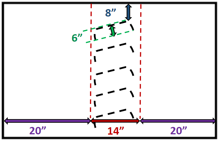
”D”: The top of the top ladder rung is 8” below the elevation of the ceiling of the inlet and is recorded as D = 8” on the P/P chart on the form.
”W”: The Ladder Rung extends 6” from the wall of the inlet – so it is recorded as W = 6”.
“L”: The ladder rungs run 14” along the wall, and is recorded as “L = 14“ on the chart. The profile views of the interior of the inlet at the bottom of the Open Curb Inlet survey Form provide the space to include where along the wall the Ladder Rungs are situated (see purple measurements on either side of the pipe image and profile view of Side 4).
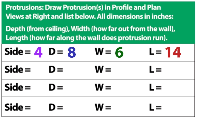
These protrusion measurement steps need to be repeated for all protrusions into the inlet open space.
